 Semiconductors


 Passive Components


 Sensors


 Power
Power


 Optoelectronics


What Is NE555N?
1. NE555N is a widely recognized integrated circuit (IC) known as the 555 timer.
2. NE555N is a type of timer IC used for timing, pulse generation, and oscillation.
3. It is packaged in a Dual In-line Package (DIP) with 8 pins, which is easy to use on breadboards and PCBs.
4. NE555N is manufactured by multiple companies and is commonly used in various electronic projects.
5. It can be used in monostable, astable, and bistable configurations.
Pinout of NE555N
Here is the pinout for the NE555N timer IC:
GND: Ground - Connects to the ground of the circuit.
Trigger: Initiates the timing interval when the voltage drops below 1/3 of Vcc.
Output: Outputs the timer signal.
Reset: Resets the timer when the voltage on this pin is driven low (active low).
Control Voltage: Modifies the threshold and trigger levels, often connected to ground via a capacitor.
Threshold: Monitors the voltage to determine when to end the timing interval.
Discharge: Discharges the timing capacitor to stop the timing interval.
Vcc: Supply voltage - Powers the IC, typically between 4.5V to 15V.
Circuits of NE555N
The NE555N timer IC relies on internal comparators, current sources, and amplifiers. The basic flow of the circuit includes the triggering of input signals, the generation of output signals, and the charging and discharging process of timing elements.
In the monostable mode of the NE555N, when the trigger pin receives a low-level signal, the internal circuit sets the output pin to high. At this point, the capacitor connected to the threshold pin begins to charge until the voltage reaches 2/3 Vcc, at which point the timer resets, and the output returns to low. During this process, the discharge pin discharges the capacitor, completing one timing cycle.
In the stable mode of the NE555N, the state changes of the trigger and reset pins control the switching of the output state. When the trigger pin receives a low-level signal, the output becomes high; conversely, when the reset pin receives a low-level signal, the output is forced to low.
Specification of NE555N
Supply Voltage (Vcc): 4.5V ~ 16V
Output Current: Up to 200 mA
Timing Range: Microseconds to hours
Threshold Voltage: 2/3 Vcc
Trigger Voltage: 1/3 Vcc
Frequency: 500kHz
Temperature Range: 0°C ~ 70°C
Package Type: DIP-8
Output Type: Push-pull (bipolar)
Features of NE555N
Exact equivalent in most cases for SE/NE555
Low Supply Current
High Speed Operation - 500KHz Guaranteed
Wide operation Supply Voltage Range - 2V to 18V
Timing from Microseconds Through Hours
Operates in Both Astable and Monostable Modes
Adjustable Duty Cycle
High Output Source/Sink Driver Can Drive TTL/CMOS
Applications of NE555N
Precision Timing
Pulse Generation
Sequential Timing
Time Delay Generation
Pulse Width Modulation
Pulse Position Modulation
Missing Pulse Detector
Package of NE555N
The NE555N comes in an 8-DIP format, making it easy to install on breadboards and printed circuit boards (PCBs). The 8-DIP package features 8 pins arranged in two parallel rows, which is ideal for projects with limited space. This package type offers benefits such as good heat dissipation and convenient pin connections, making it suitable for rapid prototyping and experimentation.
Where to Use NE555N?
The NE555N timer IC is widely used in various electronic projects, especially in circuits that require timing, pulse generation, and oscillator functions. It can be used to design monostable, astable oscillators, and pulse width modulation (PWM) circuits, with common applications including LED flashers, buzzer drivers, and timing delay circuits.
Additionally, the NE555N is employed in industrial control, automation devices, and audio signal processing, such as in motor control, frequency detection, and signal generator applications.
How to Select and Use NE555N?
When selecting and using the NE555N timer IC, it is essential to first consider the specific requirements of your circuit. Depending on the application, the NE555N can be used for generating timing signals, pulse signals, or as an oscillator. Therefore, when choosing, you should focus on its operating mode, voltage range, and load capacity. Next, determine if additional components such as resistors and capacitors are needed to achieve the desired time constant.
During the operation process, first, turn off the power and correctly connect the NE555N pins according to the circuit diagram. For example, connect the trigger pin to the input signal source, the output pin to the load control circuit, and place a capacitor between the threshold and discharge pins to set the timing period. After powering on, observe the changes in the output signal to ensure the circuit functions as expected. If you need to adjust the timing period, you can change the resistor or capacitor values. During testing, you can use an oscilloscope to monitor the output waveform.
FAQs
What are the operating modes of the NE555N?
The NE555N operates in three modes: monostable (one-shot pulse generation), astable (oscillator mode for continuous pulses), and bistable (flip-flop or toggle mode).
How do I set the timing for the NE555N?
Timing in the NE555N is controlled by external resistors and capacitors connected to the Threshold and Discharge pins. The values of these components determine the duration of the timing cycle.
What should I do if the NE555N doesn't work as expected?
Check the connections and the values of external components like resistors and capacitors. Ensure the power supply voltage is within the operating range and inspect the circuit for any shorts or incorrect wiring.
The Products You May Be Interested In
 |
EP3000AC48IN | AC/DC CONVERTER 52V 3000W | 310 More on Order |
 |
XSC003A5F91Z | DC DC CONVERTER | 399 More on Order |
|
AXH010A0MZ | DC DC CONVERTER 1.5V 15W | 351 More on Order |
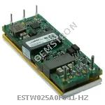 |
ESTW025A0F641-HZ | DC DC CONVERTER 3.3V 83W | 250 More on Order |
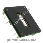 |
JRCW016A0R64-18Z | DC DC CONVERTER 28V 448W | 149 More on Order |
 |
FNW500R64-18Z | DC DC CONVERTER 28V 500W | 477 More on Order |
 |
EVW020A0A41Z | DC DC CONVERTER 5V 100W | 320 More on Order |
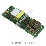 |
EQW020A0A1Z | DC DC CONVERTER 5V 100W | 383 More on Order |
 |
ATA006A0X4Z | DC DC CONVERTER 0.8-5.5V 33W | 289 More on Order |
 |
QRW025A0A | DC DC CONVERTER 5V 125W | 482 More on Order |
|
MC005C | DC DC CONVERTER 15V 5W | 158 More on Order |
|
LW015F94 | DC DC CONVERTER 3.3V 15W | 499 More on Order |
|
LW010F1 | DC DC CONVERTER 3.3V 10W | 150 More on Order |
|
LW010A9 | DC DC CONVERTER 5V 10W | 122 More on Order |
|
LW010A84 | DC DC CONVERTER 5V 10W | 446 More on Order |
 |
JW075F | DC DC CONVERTER 3.3V 50W | 231 More on Order |
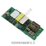 |
EQW020A0F1-S | DC DC CONVERTER 3.3V 66W | 133 More on Order |
|
AXH005A0X-SR | DC DC CONVERTER 0.8-3.6V 18W | 277 More on Order |
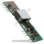 |
AXA010A0X3 | DC DC CONVERTER 0.8-5.5V 55W | 409 More on Order |
 |
QBDW033A0B641-HZ | DC DC CONVERTER 12V 400W | 372 More on Order |
|
QSDW042A0B641-HZ | DC DC CONVERTER 12V | 387 More on Order |
 |
QBVW033A0B9641-HZ | DC DC CONVERTER 12V 400W | 167 More on Order |
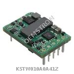 |
KSTW010A0A41Z | DC DC CONVERTER 5V 50W | 424 More on Order |
 |
PNVX002A0X3-SRZ | DC DC CONVERTER 0.6-5.5V 11W | 385 More on Order |