 Semiconductors


 Passive Components


 Sensors


 Power
Power


 Optoelectronics


What Is IR2153S?
1. The IR2153S is a high-voltage, high-speed power MOSFET and IGBT driver IC.
2. It features a built-in dead-time control.
3. The IR2153S integrates a high-voltage half-bridge gate driver.
4. The IC includes a front-end oscillator similar to the CMOS 555 timer.
5. The CT pin has a shutdown feature that allows both gate driver outputs to be disabled with a low voltage control signal.
6. The IR2153S features reduced peak di/dt of the gate drivers and increased undervoltage lockout hysteresis (1V).
7. The device is designed with maximized latch immunity and comprehensive electrostatic discharge (ESD) protection on all pins.
Pinout of IR2153S
VCC: Power supply input.
RT: Timing resistor pin, used to set the frequency of the internal oscillator.
CT: Timing capacitor pin, works with RT to set the oscillator frequency and also serves as the shutdown control.
COM: Common ground pin.
LO: Low-side gate driver output, connected to the low-side MOSFET gate.
VS: High-voltage floating supply return, connected to the source of the high-side MOSFET.
HO: High-side gate driver output, connected to the high-side MOSFET gate.
VB: High-side floating supply voltage, connected to the bootstrap capacitor and the high-side MOSFET source.
Circuit of IR2153S
The IR2153S primarily drives a half-bridge circuit consisting of two MOSFETs, with one connected to the high side (linked to the positive power supply) and the other to the low side (grounded). The IC's internal oscillator generates a square wave signal that alternately switches the MOSFETs on and off, converting the DC power supply into an AC output. In the circuit, VCC provides the operating voltage for the IC, while RT and CT determine the oscillator frequency. The bootstrap circuit supplies gate drive voltage to the high-side MOSFET through the VB and VS pins.
Specification of IR2153S
High Side Voltage - Max (Bootstrap): 600 V
Maximum VCC Voltage: 25V
Voltage - Supply: 10V ~ 15.6V
Gate Drive Peak Current: 290 mA (source), 600 mA (sink)
Oscillator Frequency Range: 20 kHz to 500 kHz
Undervoltage Lockout (UVLO): 8.4V (turn-on), 7.4V (turn-off)
Hysteresis (UVLO): 1V
Dead Time: 1.2 µs
Rise / Fall Time (Typ): 80ns, 45ns
Operating Temperature Range: -40°C ~ 125°C
Package Type: 8-SOIC
ESD Protection: 2 kV (HBM)
Features of IR2153S
Integrated 600V half-bridge gate driver
15.6V zener clamp on Vcc
True micropower start up
Tighter initial deadtime control
Low temperature coefficient deadtime
Shutdown feature (1/6th Vcc) on CT pin
Increased undervoltage lockout Hysteresis (1V)
Lower power level-shifting circuit
Constant LO, HO pulse widths at startup
Lower di/dt gate driver for better noise immunity
Low side output in phase with RT
Internal 50nsec (typ.) bootstrap diode (IR2153D)
Excellent latch immunity on all inputs and outputs
ESD protection on all leads
Also available LEAD-FREE
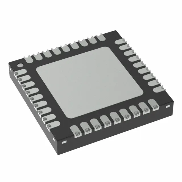
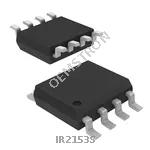
Package of IR2153S
The IR2153S is packaged in an 8-pin Small Outline Integrated Circuit (SOIC) package. This compact package is designed for surface-mount technology (SMT), offering a small footprint that is ideal for high-density circuit boards. The 8-SOIC package provides easy integration into various electronic designs, ensuring reliable performance with efficient thermal management and protection against environmental factors.
Where to Use IR2153S?
The IR2153S is an integrated high-voltage half-bridge driver and oscillator chip, widely used in circuits requiring stable switching frequencies. It is primarily designed to drive a half-bridge circuit composed of two MOSFETs, which are commonly found in various power conversion applications such as switch-mode power supplies, electronic ballasts, inverters, and motor drivers.
The IR2153S features strong noise immunity and excellent latch-up protection, enabling it to operate reliably in high-noise environments, preventing malfunctions caused by electrical noise interference. Additionally, the chip includes undervoltage lockout (UVLO) functionality to protect the MOSFETs from damage due to unstable voltage conditions, further enhancing circuit reliability.
How to Select and Use IR2153S?
First, understand the working voltage, frequency requirements, and specific power conversion needs of your circuit. Next, select the appropriate RT and CT values based on the desired switching frequency, as these determine the internal oscillator frequency. Then, ensure stable gate drive voltage for the high-side MOSFET, typically achieved by connecting a Bootstrap circuit to the VB and VS pins.
When designing the circuit, pay attention to electromagnetic compatibility (EMC) issues in the PCB layout to minimize noise interference. Additionally, correctly connect the IR2153S pins: connect VCC to a stable operating voltage source, RT and CT to the relevant oscillator components, and LO and HO to the gates of the low-side and high-side MOSFETs, respectively.
Finally, after completing the circuit design, test and adjust key parameters to ensure the IR2153S operates as expected.
FAQs
How does the IR2153S work?
The IR2153S generates alternating gate drive signals for two MOSFETs in a half-bridge configuration, converting a DC input into an AC output by alternately switching the MOSFETs on and off.
What are the key features of the IR2153S?
The IR2153S offers features like undervoltage lockout (UVLO), improved noise immunity, and a shutdown capability via the CT pin. It also has a built-in oscillator for frequency control.
What is the role of the Bootstrap circuit in the IR2153S?
The Bootstrap circuit in the IR2153S is essential for providing the necessary gate drive voltage to the high-side MOSFET. It charges a Bootstrap capacitor through the VB and VS pins, which then supplies the gate drive voltage when the high-side MOSFET is switched on.
The Products You May Be Interested In
 |
EP3000AC48INZ | AC/DC CONVERTER 52V 3000W | 316 More on Order |
 |
ATM020A0X3-SRZ | DC DC CONVERTER 0.75-2V | 447 More on Order |
|
AXH010A0F9-SR | DC DC CONVERTER 3.3V 33W | 177 More on Order |
 |
ESTW015A0A41-SZ | DC DC CONVERTER 5V 75W | 498 More on Order |
|
JRW040A0A41-PHZ | DC DC CONVERTER 5V 200W | 462 More on Order |
|
QRW010A0B641-BH | DC DC CONVERTER 12V 120W | 167 More on Order |
|
QPW060A0P641 | DC DC CONVERTER 1.2V 72W | 158 More on Order |
 |
APXH003A0X4-SRZ | DC DC CONVERTER 0.6-3.6V 10W | 282 More on Order |
 |
ATH030A0X3-PZ | DC DC CONVERTER 0.8-3.6V 108W | 148 More on Order |
|
SE014S110 | DC DC CONVERTER 110V 14W | 178 More on Order |
|
QW020A0M1 | DC DC CONVERTER 1.5V 30W | 389 More on Order |
|
LW015D981 | DC DC CONVERTER 2V 15W | 227 More on Order |
|
LW010CL | DC DC CONVERTER +/-15V 10W | 458 More on Order |
 |
JW050A8 | DC DC CONVERTER 5V 50W | 315 More on Order |
|
JRW065A0G1 | DC DC CONVERTER 2.5V 163W | 465 More on Order |
|
JRW017A0B1 | DC DC CONVERTER 12V 204W | 320 More on Order |
 |
JAW075A | DC DC CONVERTER 5V 75W | 455 More on Order |
 |
JAHW100Y1 | DC DC CONVERTER 1.8V 36W | 416 More on Order |
 |
HW006A0M1-S | DC DC CONVERTER 1.5V 9W | 221 More on Order |
 |
HW006A0D1-S | DC DC CONVERTER 2V 12W | 156 More on Order |
 |
QBVW025A0B41-HZ | DC DC CONVERTER 12V 300W | 108 More on Order |
 |
ATH010A0X3Z | DC DC CONVERTER 0.8-3.6V 36W | 442 More on Order |
 |
PVX006A0X43-SRZ | DC DC CONVERTER 0.6-5.5V 33W | 474 More on Order |
 |
ESTW004A2C41-HZ | DC DC CONVERTER 15V 63W | 342 More on Order |