 Semiconductors


 Passive Components


 Sensors


 Power
Power


 Optoelectronics


What Is L6219DS?
The L6219DS is a motor driver designed to control bipolar stepper motors or two DC motors with bidirectional drive capability. It features two H-bridge outputs that can handle up to 45 V and provide up to 750 mA of current. The device incorporates internal PWM control to regulate output current, with a low saturation voltage drop of less than 1.8 V at 500 mA.
The output current limit is adjustable using a reference voltage and sensing resistor, with logic-level inputs allowing for current limits of 0%, 33%, 67%, or 100%. The motor direction is controlled via a PHASE input. The L6219DS also includes built-in protection features such as ground clamp and flyback diodes for inductive transient protection, as well as thermal protection that disables outputs if the chip exceeds safe temperature limits.
Pinout of L6219DS
1. COMP_IN1 - Comparator input 1
2. COMP_IN2 - Comparator input 2
3. I01 - Current sense input 1 (for motor 1)
4. I02 - Current sense input 2 (for motor 1)
5. I11 - Current sense input 1 (for motor 2)
6. I12 - Current sense input 2 (for motor 2)
7. PHASE1 - Phase input for motor 1 (determines direction)
8. PHASE2 - Phase input for motor 2 (determines direction)
9. RC1 - External resistor for current sensing (motor 1)
10. RC2 - External resistor for current sensing (motor 2)
11. SENSE1 - Current sensing input (motor 1)
12. SENSE2 - Current sensing input (motor 2)
13. VREF1 - Reference voltage for motor 1
14. VREF2 - Reference voltage for motor 2
15. GROUND - Ground connection
16. OUT2B - Output B for motor 2
17. OUT2A - Output A for motor 2
18. OUT1B - Output B for motor 1
19. OUT1A - Output A for motor 1
20. LOAD_SUPPLY - Power supply for the motor load
21. LOGIC_SUPPLY - Power supply for logic circuitry
Circuit Operation of L6219DS
The L6219DS driver controls the forward and reverse rotation of a motor using two H-bridge circuits. Each bridge circuit has corresponding phase control inputs to determine the direction of current. When the motor current direction changes, an internal delay circuit prevents crossover currents.
Current control is determined by an external reference voltage and current sensing resistors. By adjusting the reference voltage, the user can set the maximum output current and use logic inputs to select the percentage of the current. PWM control adjusts the average output current through internal circuitry, with a maximum current of 750mA.
During operation, the L6219DS output terminals drive the motor load based on the input control signals. Each bridge output terminal includes ground voltage clamps and flyback diodes to protect the circuit from inductive load-induced reverse current spikes.
Specification of L6219DS
Output Configuration: Half Bridge (4)
Step Resolution: 1, 1/2
Supply Voltage: 4.75V ~ 5.25V
Output Current (per bridge): 750mA
Load Voltage: 10V ~ 45V
PWM Frequency: 20 kHz
Current Limit: 0%, 33%, 67%, or 100% of maximum current
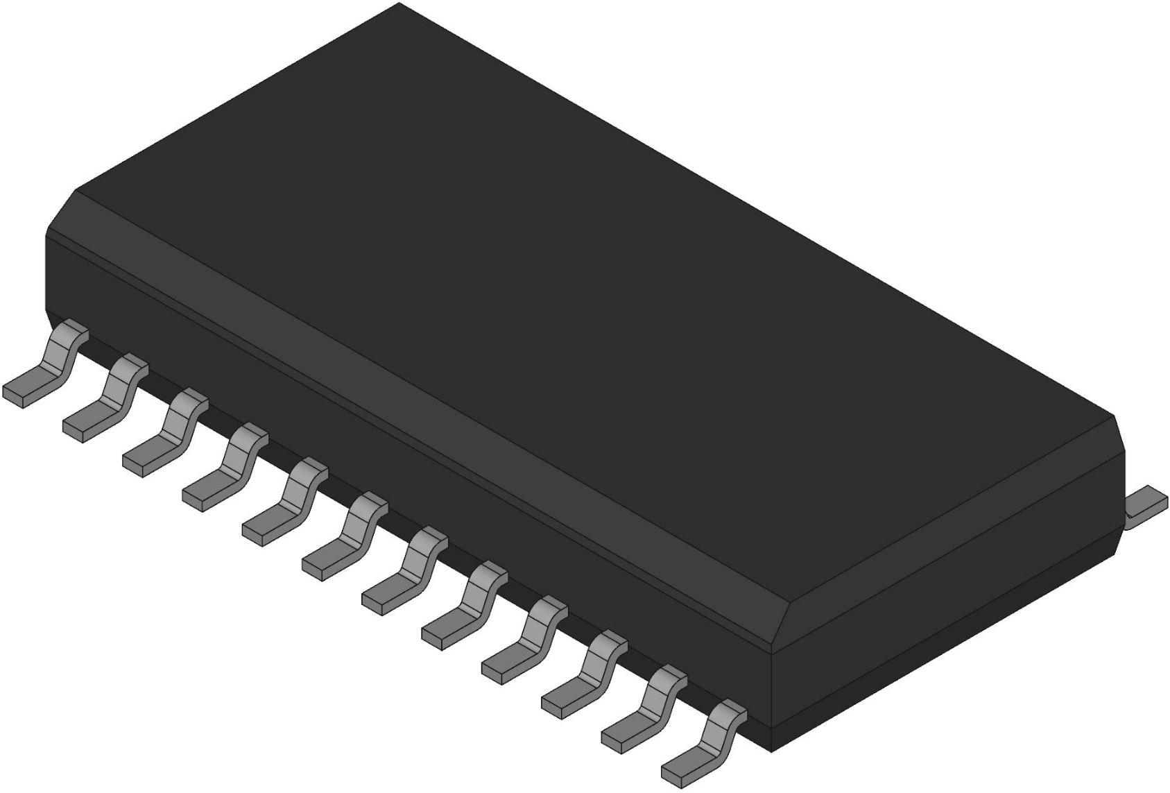
Package Type: 24-SOIC
Operating Temperature: -20°C ~ 150°C
Lead Material: Lead-free, 100% matte tin plating
Features of L6219DS
Interchangeable with SGS L6219DS
750 mA Continuous Output Current
45 V Output Sustaining Voltage
Internal Clamp Diodes
Internal PWM Current Control
Low Output Saturation Voltage
Internal Thermal Shutdown Circuitry
Similar to Dual PBL3717, UC3770
Applications of L6219DS
PWM Current Control
Current Sensing
Thermal Considerations
Load Supply Terminal
Fixed Off-Time Selection
Logic Control of Output Current
Where to Use L6219DS?
The L6219DS driver is widely used for controlling stepper motors or DC motors. With its dual H-bridge design, it can drive bidirectional control of DC motors or bipolar stepper motors with dual windings, making it particularly suitable for applications like automation equipment, robotics, printers, scanners, and other systems requiring precise motor control.
Additionally, due to its over-temperature and over-current protection features, the L6219DS is also well-suited for high-power motor control systems, ensuring stable operation while preventing damage to the motor or driver.
How to Connect L6219DS?
First, supply power to the L6219DS. Connect the LOAD_SUPPLY pin to the positive terminal of the motor driver power supply. Connect the GROUND pin to the negative terminal of the power supply. The LAGIC_SUPPLY pin should be connected to an appropriate logic power supply.
Next, connect the two windings of the motor to the output pins OUT1A, OUT1B, and OUT2A, OUT2B. Then, connect the phase control pins PHASE1 and PHASE2 to the control signal source. When the motor direction needs to change, the control signal will change the phase input accordingly. Use the SENSE1 and SENSE2 pins to connect current sensing resistors for PWM current control.
Set the maximum current by connecting a reference voltage to the VREF1 and VREF2 pins. Adjust the reference voltage as needed to ensure the driver can provide the desired current. To select the current limit, use the logic input pins to choose 0%, 33%, 67%, or 100% of the maximum current output.
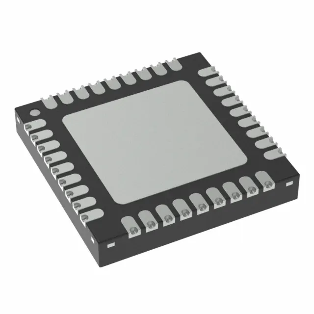
Package of L6219DS
The L6219DS comes in a 24-pin SOIC package, designed for surface-mount applications. The 24-SOIC package provides a compact and efficient layout, allowing for better thermal dissipation and reduced PCB space requirements. The package dimensions are typically 10.3 mm x 7.5 mm with a 1.27 mm pitch between pins.
It is a lead (Pb)-free design with 100% matte tin leadframe plating, ensuring compliance with RoHS standards. This type of package is ideal for automotive, industrial, and consumer electronics applications where space-saving and reliable performance are crucial.
FAQs
Can the L6219DS be used for bidirectional control?
Yes, the L6219DS can control the direction of current flow in both DC motors and stepper motors through its H-bridge design and phase control inputs.
What types of motors can the L6219DS drive?
The L6219DS can drive both bipolar stepper motors and bidirectional DC motors, making it versatile for various motor control applications.
Is there any special consideration when using the L6219DS?
It's important to ensure the motor is disconnected from the power supply before changing configurations, and appropriate heat sinking or PCB layout is used for thermal management due to its high power dissipation in motor control applications.
The Products You May Be Interested In
 |
EP1000-UTEZ | AC/DC CONVERTER 52V 1000W | 480 More on Order |
 |
CAR2548DCXXXZ01A | DC/DC CONVERTER 48V 2500W | 498 More on Order |
 |
EHHD036A0F41-SZ | DC DC CONVERTER 3.3V 120W | 255 More on Order |
 |
AXH010A0Y | DC DC CONVERTER 1.8V 18W | 395 More on Order |
|
AXH010A0M9-SR | DC DC CONVERTER 1.5V 15W | 164 More on Order |
|
AXH010A0G5 | DC DC CONVERTER 2.5V 25W | 437 More on Order |
|
AXH010A0F-SRZ | DC DC CONVERTER 3.3V 33W | 255 More on Order |
 |
EQW020A0A4-HZ | DC DC CONVERTER 5V 100W | 163 More on Order |
|
QRW035A0F61 | DC DC CONVERTER 3.3V 116W | 337 More on Order |
|
QPW060A0P41 | DC DC CONVERTER 1.2V 72W | 319 More on Order |
 |
QPW050A0F1Z | DC DC CONVERTER 3.3V 165W | 475 More on Order |
 |
QRW025A0G41 | DC DC CONVERTER 2.5V 63W | 465 More on Order |
|
QHW075G71 | DC DC CONVERTER 2.5V 38W | 272 More on Order |
|
LW010A981 | DC DC CONVERTER 5V 10W | 405 More on Order |
|
LW005F84 | DC DC CONVERTER 3.3V 5W | 371 More on Order |
|
FW250A1 | DC DC CONVERTER 5V 250W | 348 More on Order |
 |
EQW020A0F1-S | DC DC CONVERTER 3.3V 66W | 133 More on Order |
 |
DW025ABK-M | DC DC CONVERTER 5V +/-12V 25W | 395 More on Order |
 |
QBVW025A0B841Z | DC DC CONVERTER 12V 300W | 298 More on Order |
|
ERCW003A6R41Z | DC DC CONVERTER 28V | 145 More on Order |
 |
SHHN000A3CL41Z | DC DC CONVERTER +/-15V 9W | 245 More on Order |
 |
MVT040A0X3-SRPHZ | DC DC CONVERTER 0.6-2V 40A | 319 More on Order |
 |
PKX020A0X43-SRZ | DC DC CONVERTER 0.6-3.63V | 341 More on Order |
 |
QSVW050A0B41-PHZ | 36-75VIN, 50A/12V OUT, 600W, 1/4 | 266 More on Order |